Contents
Introduction
This document describes how to troubleshoot a packet over SONET (POS) router interface that has a line protocol status of «down».
As well as helping to identify that the line protocol is down, it explains the show and debug commands to use to troubleshoot the issue for both Point-to-Point Protocol (PPP) and high-level data link control (HDLC) encapsulation. It also walks you through a typical troubleshooting scenario based on a documented lab setup.
Interpret the show interface pos Command
For the purposes of document, the output of show interface pos is as this output shows. Note the highlighted parts of the display and comments:
RTR12410-2#show interface pos 6/0
   POS6/0 is up, line protocol is down

!--- The line protocol is down
.
     Hardware is Packet over SONET
  MTU 4470 bytes, BW 2488000 Kbit, DLY 100 usec, rely 255/255, load 1/255
     Encapsulation HDLC, crc 32, loopback not set

!--- The loopback has not been set.

     Keepalive set (10 sec)

!--- The keepalive is set as every ten seconds.

     Scramble disabled
  Last input never, output 00:00:05, output hang never
  Last clearing of "show interface" counters never
  Queueing strategy: fifo
  Output queue 0/40, 0 drops; input queue 0/75, 0 drops
  5 minute input rate 0 bits/sec, 0 packets/sec
  5 minute output rate 0 bits/sec, 0 packets/sec
     0 packets input, 0 bytes, 0 no buffer
     Received 0 broadcasts, 0 runts, 0 giants, 0 throttles
              0 parity
     0 input errors, 0 CRC, 0 frame, 0 overrun, 0 ignored, 0 abort
     3 packets output, 1074 bytes, 0 underruns
     0 output errors, 0 applique, 1 interface resets
     0 output buffer failures, 0 output buffers swapped out
     2 carrier transitions
The Cisco IOS® Command Reference states that the line protocol field status «indicates whether the software processes that handle the line protocol consider the line usable (that is, keepalives are successful) or whether it has been taken down by an administrator.»
Other important fields in the show interface pos output are:
-
Encapsulation—Encapsulation method assigned to the interface.
-
loopback—Indicates whether loopback is set.
-
keepalive—Indicates whether keepalives are set.
POS Protocol Stack Overview
This diagram illustrates the protocol stack used on a POS interface.
POS interfaces support multiple encapsulations — HDLC, PPP and Frame Relay. Thus, packet over SONET is more accurately PPP over SONET or HDLC over SONET. This document does not cover Frame Relay encapsulation.
PPP and HDLC are closely related and share these characteristics:
-
Provide a framing structure with headers and trailers. The trailer provides error checking.
-
Provide frame delineation, which defines for a receiver exactly where a packet and frame begins and ends. In HDLC and PPP, frame delineation is provided by means of a special interframe fill pattern or idle pattern. The pattern is 0x7E, or 0111 1110.
-
Define a minimum and maximum packet length.
-
Transport IP packets and provide a method for receivers to determine the precise type of packet inside the arriving frame.
However, although closely related, PPP and HDLC are not the same, and different debug commands are used to troubleshoot line protocol problems.
Use debug Commands
The output of various debug privileged EXEC commands provides diagnostic information related to protocol status and network activity for many internetworking events.
 Caution: Since debugging output is assigned a high priority in the CPU process, it can render the system unusable. For this reason, use debug commands only to troubleshoot specific problems or during troubleshooting sessions with Cisco technical support staff. Moreover, it is best to use debug commands during periods of low network traffic and fewer users. Debugging during these periods decreases the likelihood that increased debug command processing overhead affects system use. When you finish using a debug command, remember to disable it with its specific no debug command or with the no debug all command.
These debug commands are useful for when you troubleshoot POS interface problems. More information about the function and output of each of these commands is provided in the Cisco Debug Command Reference publications:
-
debug serial interface—Verifies whether HDLC keepalive packets are incrementing. If they are not, a possible timing problem exists on the interface card or in the network.
-
debug ppp negotiation—Shows PPP packets transmitted during PPP startup, where PPP options are negotiated.
-
debug ppp packet—Shows PPP packets being sent and received. This command displays low-level packet dumps.
-
debug ppp errors—Shows PPP errors (such as illegal or malformed frames) associated with PPP connection negotiation and operation.
Refer to Troubleshooting Serial Line Problems for more information.
Line Protocol Is Down With HDLC
HDLC is the default encapsulation type on a POS router interface. HDLC is an international standard, but vendor implementations vary one or more fields or the header or trailer in size and format. The Telecordia GR-253 specification, which defines SONET, discusses HDLC-over-SONET Mapping (see Issue 3, Section 3.4.2.3, pp.3-59.) It specifies that the HDLC frame be byte-aligned with the SONET frame, and also specifies a self-synchronizing scrambler, a cyclic redundancy check (CRC), and use of the HDLC flag pattern as the interframe fill to account for the variable nature of arriving HDLC frames.
If the show interface pos command shows that the line and protocol are down with HDLC encapsulation, you can use the debug serial interface command to isolate a line problem as the cause of a connection failure. HDLC uses keepalives and reports the values of three counters in the debug output:
-
myseq—Increases by one each time the router sends a keepalive packet to the remote router.
-
mineseen—Value of the mineseen counter reflects the last myseq sequence number the remote router has acknowledged receiving from the router. The remote router stores this value in its yourseen counter and sends that value in a keepalive packet to the router.
-
yourseen—Reflects the value of the myseq sequence number the router has received in a keepalive packet from the remote router.
If the keepalive values in the mineseq, yourseen, and myseen fields are not incrementing in each subsequent line of output, there is a problem at one end of the connection. When the difference in the values in the myseq and mineseen fields exceeds three, the line goes down and the interface is reset.
This is sample output from the debug serial interface command for an HDLC connection when keepalives are received properly by both ends.
hswan-12008-2a#debug serial interface
Serial network interface debugging is on
hswan-12008-2a#
Oct 31 11:47:16: POS4/0: HDLC myseq 180, mineseen 0*, yourseen 1, line up
Oct 31 11:47:17: %LINEPROTO-5-UPDOWN: Line protocol on Interface POS4/0,
changed state to up

!--- Local router sees a remote keepalive with a sequence number of 1.

Oct 31 11:47:26: POS4/0: HDLC myseq 181, mineseen 181*, yourseen 2, line up
Oct 31 11:47:36: POS4/0: HDLC myseq 182, mineseen 182*, yourseen 3, line up
Oct 31 11:47:46: POS4/0: HDLC myseq 183, mineseen 183*, yourseen 4, line up
Oct 31 11:47:56: POS4/0: HDLC myseq 184, mineseen 184*, yourseen 5, line up
Oct 31 11:48:06: POS4/0: HDLC myseq 185, mineseen 185*, yourseen 6, line up

!--- Keepalives are sent every 10 seconds by default. !--- Both sides report incrementing sequence numbers.
This is sample output from the debug serial interface command for an HDLC connection when the remote interface is shut and the local interface misses more than three keepalives.
hswan-12008-2a#
Oct 31 11:49:46: POS4/0: HDLC myseq 195, mineseen 192, yourseen 13, line down
Oct 31 11:49:47: %LINEPROTO-5-UPDOWN: Line protocol on Interface POS4/0,
changed state to down

!--- The local router has failed to receive three keepalives and !--- brings down the line protocol. Note the difference between !--- "myseq 195" and "mineseen 192".

Oct 31 11:49:56: POS4/0: HDLC myseq 196, mineseen 192, yourseen 13, line down
Oct 31 11:50:06: POS4/0: HDLC myseq 197, mineseen 192, yourseen 13, line down
Oct 31 11:50:16: POS4/0: HDLC myseq 198, mineseen 192, yourseen 13, line down
Oct 31 11:50:26: POS4/0: HDLC myseq 199, mineseen 192, yourseen 13, line down
Oct 31 11:50:36: POS4/0: HDLC myseq 200, mineseen 0*, yourseen 1, line up
Oct 31 11:50:37: %LINEPROTO-5-UPDOWN: Line protocol on Interface POS4/0,
changed state to up

!--- After you execute the no shut command on the remote router, !--- the local router receives a keepalive again and brings up !--- the line protocol.

Oct 31 11:50:46: POS4/0: HDLC myseq 201, mineseen 201*, yourseen 2, line up
Oct 31 11:50:56: POS4/0: HDLC myseq 202, mineseen 202*, yourseen 3, line up
Oct 31 11:51:06: POS4/0: HDLC myseq 203, mineseen 203*, yourseen 4, line up
Oct 31 11:51:16: POS4/0: HDLC myseq 204, mineseen 204*, yourseen 5, line up
Oct 31 11:51:26: POS4/0: HDLC myseq 205, mineseen 205*, yourseen 6, line up
Oct 31 11:51:36: POS4/0: HDLC myseq 206, mineseen 206*, yourseen 7, line up

!--- After the shut/no shut, the remote router re-initialized its !--- sequence number.
Line Protocol Is Down With PPP
RFC 1661 ![]() defines PPP as a protocol. POS interfaces support PPP in High-Level Data Link Control (HDLC)-like framing, as specified in RFC 1662
defines PPP as a protocol. POS interfaces support PPP in High-Level Data Link Control (HDLC)-like framing, as specified in RFC 1662 ![]() , for data encapsulation at Layer 2. The frame format for PPP in HDLC-like framing is shown in this figure.
, for data encapsulation at Layer 2. The frame format for PPP in HDLC-like framing is shown in this figure.

RFC 2615 specifies the use of PPP encapsulation over SONET or SDH links. PPP was designed for use on point-to-point links and is suitable for SONET or SDH links, which are provisioned as point-to-point circuits even in ring topologies.
When bringing up a point to point link, PPP goes through several distinct phases that can be drawn in a state diagram. When an external event, such as carrier detection or network administrator configuration, indicates that the physical layer is ready to be used, PPP proceeds to the link establishment phase. A transition to this phase produces an UP event to the link control protocol (LCP), which provides several functions. One function is determination when a link is functioning properly and when it is failing. In order to establish communication over a point-to-point link, each end of the PPP link must first send LCP packets to configure and test the data link.
Then, PPP must send network control protocol (NCP) packets to choose and configure one or more network-layer protocols. Once each of the chosen network-layer protocols has been configured, datagrams from each network-layer protocol can be sent over the link.
This table lists the three classes of LCP packets:
| LCP Packet Class | LCP Packet Types | Purpose |
|---|---|---|
| Link Configuration | Configure-Request, Configure-Ack, Configure-Nak and Configure-Reject | Used to establish and configure a link. |
| Link Termination | Terminate-Request and Terminate-Ack | Used to terminate a link. |
| Link Maintenance | Code-Reject, Protocol-Reject, Echo-Request, Echo-Reply, and Discard-Request | Used to manage and debug a link. |
Link Configuration
LCP is used to establish the connection through an exchange of Configure packets. This exchange is complete, and the LCP Opened state entered, once a Configure-Ack packet has been both sent and received.
This sample output captures the LCP link configuration stage on a POS interface:
4d01h: PO3/1 LCP: State is Open
4d01h: PO3/1 PPP: I pkt type 0x8021, datagramsize 14 LCP_UP
(0x639FCAD8) id 0 (0s.) queued 1/1/2
4d01h: PO3/1 PPP: Phase is UP
4d01h: PO3/1 IPCP: O CONFREQ [Closed] id 152 len 10
4d01h: PO3/1 IPCP:    Address 172.16.1.1 (0x0306AC100101)
4d01h: PO3/1 PPP: I pkt type 0x8021, datagramsize 14
4d01h: PO3/1 IPCP: I CONFREQ [REQsent] id 1 len 10
4d01h: PO3/1 IPCP:    Address 172.16.1.2 (0x0306AC100102)
4d01h: PO3/1 IPCP: O CONFACK [REQsent] id 1 len 10
4d01h: PO3/1 IPCP:    Address 172.16.1.2 (0x0306AC100102)
4d01h: PO3/1 IPCP: I CONFACK [ACKsent] id 152 len 10
4d01h: PO3/1 IPCP:    Address 172.16.1.1 (0x0306AC100101)
4d01h: PO3/1 IPCP: State is Open
4d01h: PO3/1 IPCP: Install route to 172.16.1.2
4d01h: %LINEPROTO-5-UPDOWN: Line protocol on Interface POS3/1,
changed state to up
Note: A POS interface configured with PPP encapsulation continually tries to establish a PPP session. Thus, you see the line protocol come up briefly on a periodic basis when there is a sustained problem, even when the fiber is removed.
Link Maintenance (With Keepalives)
LCP Echo-Request and Echo-Reply packets provide a Layer 2 loopback mechanism for both directions of the link. On reception of an Echo-Request in the LCP Opened state, an Echo-Reply must be transmitted.
This diagram from RFC 1661 illustrates the format of a PPP keepalive packet.
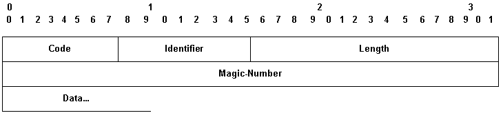
These LCP packets include these key fields:
-
Code—9 for Echo-Request and 10 for Echo-Reply.
-
Identifier—On transmission, the Identifier field must be changed whenever the content of the Data field changes and whenever a valid reply has been received for a previous request. For retransmissions, the Identifier may remain unchanged. On reception, the Identifier field of the Echo-Request is copied into the Identifier field of the Echo-Reply packet.
-
Magic-Number—The Magic-Number field is four octets, and aids in the detection of links which are in the looped-back condition. Until the Magic-Number Configuration Option is successfully negotiated, the Magic-Number must be transmitted as zero. See the Magic-Number Configuration Option in RFC 1661 for further explanation.
-
Data—The Data field is zero or more octets, and contains uninterpreted data for use by the sender. The data may consist of any binary value. The end of the field is indicated by the Length.
Here is an example of debug ppp negotiation when keepalives are enabled:
4d01h: PO3/1 LCP: O ECHOREQ [Open] id 1 len 12 magic 0x1A45933B
4d01h: PO3/1 PPP: I pkt type 0xC021, datagramsize 16
4d01h: PO3/1 LCP: I ECHOREP [Open] id 1 len 12 magic 0x00000002
4d01h: PO3/1 LCP: Received id 1, sent id 1, line up
Link Termination
PPP can terminate the link at any time. Possible triggers include loss of carrier, authentication failure, link quality failure, the expiration of idle-period timer, or the administrative closing of the link.
LCP uses Terminate packets to close the link. The sender of the Terminate-Request should disconnect after receiving a Terminate-Ack, or after the Restart counter expires. The receiver of a Terminate-Request should wait for the peer to disconnect, and must not disconnect until at least one Restart time has passed after sending a Terminate-Ack.
Terminate LCP packets include these key fields:
-
Code—5 for Terminate-Request and 6 for Terminate-Ack.
-
Identifier—On transmission, the Identifier field must be changed whenever the content of the Data field changes, and whenever a valid reply has been received for a previous request. For retransmissions, the Identifier can remain unchanged. On reception, the Identifier field of the Terminate-Request is copied into the Identifier field of the Terminate-Ack packet.
The Data field is zero or more octets, and contains uninterpreted data for use by the sender. The data can consist of any binary value. The end of the field is indicated by the Length.
Here is an example of debug ppp negotiation output when you receive a TERMREQ packet:
4d01h: PO3/1 PPP: I pkt type 0xC021, datagramsize 8
4d01h: PO3/1 LCP: I TERMREQ [Open] id 4 len 4
4d01h: PO3/1 LCP: O TERMACK [Open] id 4 len 4
4d01h: PO3/1 PPP: I pkt type 0xC021, datagramsize 18
4d01h: PO3/1 IPCP: State is Closed
4d01h: PO3/1 PPP: Phase is TERMINATING
4d01h: PO3/1 LCP: I CONFREQ [TERMsent] id 1 len 14
4d01h: PO3/1 LCP:    MRU 1500 (0x010405DC)
4d01h: PO3/1 LCP:    MagicNumber 0x00000002 (0x050600000002)
4d01h: PO3/1 LCP: Dropping packet, state is TERMsent

!--- While in the TERMsent state, PPP should drop all other packets.

4d01h: PO3/1 IPCP: Remove route to 172.16.1.2
4d01h: %LINEPROTO-5-UPDOWN: Line protocol on Interface POS3/1,
changed state to down
Sample Troubleshooting Sequence
This section describes a sample troubleshooting scenario for a POS link using PPP encapsulation. It uses these configurations:
| Router A Configuration |
|---|
interface POS1/0 ip address 1.1.1.6 255.255.255.0 no ip directed-broadcast encapsulation ppp crc 16 clock source internal |
| Router B Configuration |
|---|
interface POS2/0 ip address 1.1.1.5 255.255.255.0 no ip directed-broadcast encapsulation ppp crc 16 |
Note: These debugs were captured on two routers in a back-to-back lab setup. Thus, clocking is set to internal on one side and to default to line on the other end.
debug ppp negotiation
This output illustrates the packet exchange captured with debug ppp negotiation during LCP’s link establishment phase.
| Router A Debug Output |
|---|
Router A Debug Output
(1)

!--- The router sends an outgoing confreq.

hswan-12008-2a#
*Nov  7 08:27:00: %LINK-3-UPDOWN: Interface POS1/0, changed state to up
*Nov  7 08:27:00: PO1/0 PPP: Treating connection as a dedicated line
*Nov  7 08:27:00: PO1/0 PPP: Phase is ESTABLISHING, Active Open
*Nov  7 08:27:00: PO1/0 LCP: O CONFREQ [Closed] id 7 len 14
*Nov  7 08:27:00: PO1/0 LCP:    MRU 4470 (0x01041176)
*Nov  7 08:27:00: PO1/0 LCP:    MagicNumber 0x4F46AF4D (0x05064F46AF4D)
|
(4)

!--- Router A receives an incoming confreq from router B.

*Nov  7 08:27:00: PO1/0 LCP: I CONFREQ [REQsent] id 45 len 14
*Nov  7 08:27:00: PO1/0 LCP: MRU 4470 (0x01041176)
*Nov  7 08:27:00: PO1/0 LCP: MagicNumber 0x2631E6D2 (0x05062631E6D2)
|
(5)

!--- Router A responds with a confack and receives a !--- confack from Router B. The LCP state is open.

*Nov  7 08:27:00: PO1/0 LCP: O CONFACK [REQsent] id 45 len 14
*Nov  7 08:27:00: PO1/0 LCP:    MRU 4470 (0x01041176)
*Nov  7 08:27:00: PO1/0 LCP:    MagicNumber 0x2631E6D2 (0x05062631E6D2)
*Nov  7 08:27:00: PO1/0 LCP: I CONFACK [ACKsent] id 7 len 14
Nov  7 08:27:00: PO1/0 LCP:    MRU 4470 (0x01041176)
*Nov  7 08:27:00: PO1/0 LCP: MagicNumber 0x4F46AF4D (0x05064F46AF4D)
*Nov  7 08:27:00: PO1/0 LCP: State is Open
*Nov  7 08:27:00: PO1/0 PPP: Phase is UP
|
(7)

!--- Router A begins the IPCP stage and negotiates an IP address. !--- In this setup, the peer router already has an address and !--- sends it in a confreq. If the peer router accepts the address, !--- it responds with a confack.

*Nov  7 08:27:00: PO1/0 IPCP: O CONFREQ [Closed] id 7 len 10
*Nov  7 08:27:00: PO1/0 IPCP: Address 1.1.1.6 (0x030601010106)
*Nov  7 08:27:00: PO1/0 CDPCP: O CONFREQ [Closed] id 7 len 4
*Nov  7 08:27:00: PO1/0 IPCP: I CONFREQ [REQsent] id 9 len 10
*Nov  7 08:27:00: PO1/0 IPCP: Address 1.1.1.5 (0x030601010105)
*Nov  7 08:27:00: PO1/0 IPCP: O CONFACK [REQsent] id 9 len 10
*Nov  7 08:27:00: PO1/0 IPCP: Address 1.1.1.5 (0x030601010105)
*Nov  7 08:27:00: PO1/0 CDPCP: I CONFREQ [REQsent] id 9 len 4
*Nov  7 08:27:00: PO1/0 CDPCP: O CONFACK [REQsent] id 9 len 4
*Nov  7 08:27:00: PO1/0 IPCP: I CONFACK [ACKsent] id 7 len 10
*Nov  7 08:27:00: PO1/0 IPCP: Address 1.1.1.6 (0x030601010106)
*Nov  7 08:27:00: PO1/0 IPCP: State is Open
*Nov  7 08:27:00: PO1/0 CDPCP: I CONFACK [ACKsent] id 7 len 4
*Nov  7 08:27:00: PO1/0 CDPCP: State is Open
*Nov  7 08:27:00: PO1/0 IPCP: Install route to 1.1.1.5
*Nov  7 08:27:01: %LINEPROTO-5-UPDOWN: Line protocol on
Interface POS1/0, changed state to up
|
| Router B Debug Output |
|---|
(2)

!--- Router B receives an incoming confrq from Router A.

hswan-12008-2b#
Nov  7 10:29:19.043: PO2/0 LCP: I CONFREQ [Open] id 7 len 14
Nov  7 10:29:19.043: PO2/0 LCP:    MRU 4470 (0x01041176)
Nov  7 10:29:19.043: PO2/0 LCP:    MagicNumber 0x4F46AF4D (0x05064F46AF4D)
Nov  7 10:29:19.043: PO2/0 IPCP: State is Closed
Nov  7 10:29:19.043: PO2/0 CDPCP: State is Closed
Nov  7 10:29:19.043: PO2/0 PPP: Phase is TERMINATING
Nov  7 10:29:19.043: PO2/0 PPP: Phase is ESTABLISHING
|
(3)

!--- Router B sends its own LCP confreq.

Nov  7 10:29:19.043: PO2/0 LCP: O CONFREQ [Open] id 45 len 14
Nov  7 10:29:19.043: PO2/0 LCP:    MRU 4470 (0x01041176)
Nov  7 10:29:19.043: PO2/0 LCP:    MagicNumber 0x2631E6D2 (0x05062631E6D2)
|
(6)

!--- Router B responds with a confack and receives a confack from Router A.

The LCP state is open.
Nov  7 10:29:19.043: PO2/0 LCP: O CONFACK [Open] id 7 len 14
Nov  7 10:29:19.043: PO2/0 LCP:    MRU 4470 (0x01041176)
Nov  7 10:29:19.043: PO2/0 LCP:    MagicNumber 0x4F46AF4D (0x05064F46AF4D)
Nov  7 10:29:19.043: PO2/0 IPCP: Remove route to 1.1.1.6
Nov  7 10:29:19.047: PO2/0 LCP: I CONFACK [ACKsent] id 45 len 14
Nov  7 10:29:19.047: PO2/0 LCP:    MRU 4470 (0x01041176)
Nov  7 10:29:19.047: PO2/0 LCP:    MagicNumber 0x2631E6D2 (0x05062631E6D2)
Nov  7 10:29:19.047: PO2/0 LCP: State is Open
Nov  7 10:29:19.047: PO2/0 PPP: Phase is UP
|
(8)

!--- Router B also begins the IPCP stage and negotiates an IP address.

Nov  7 10:29:19.047: PO2/0 IPCP: O CONFREQ [Closed] id 9 len 10
Nov  7 10:29:19.047: PO2/0 IPCP:    Address 1.1.1.5 (0x030601010105)
Nov  7 10:29:19.047: PO2/0 CDPCP: O CONFREQ [Closed] id 9 len 4
Nov  7 10:29:19.047: PO2/0 IPCP: I CONFREQ [REQsent] id 7 len 10
Nov  7 10:29:19.047: PO2/0 IPCP:    Address 1.1.1.6 (0x030601010106)
Nov  7 10:29:19.047: PO2/0 IPCP: O CONFACK [REQsent] id 7 len 10
Nov  7 10:29:19.047: PO2/0 IPCP:    Address 1.1.1.6 (0x030601010106)
Nov  7 10:29:19.047: PO2/0 CDPCP: I CONFREQ [REQsent] id 7 len 4
Nov  7 10:29:19.047: PO2/0 CDPCP: O CONFACK [REQsent] id 7 len 4
Nov  7 10:29:19.047: PO2/0 IPCP: I CONFACK [ACKsent] id 9 len 10
Nov  7 10:29:19.047: PO2/0 IPCP:    Address 1.1.1.5 (0x030601010105)
Nov  7 10:29:19.047: PO2/0 IPCP: State is Open
Nov  7 10:29:19.047: PO2/0 CDPCP: I CONFACK [ACKsent] id 9 len 4
Nov  7 10:29:19.047: PO2/0 CDPCP: State is Open
Nov  7 10:29:19.047: PO2/0 IPCP: Install route to 1.1.1.6
*Nov  7 10:29:19.048: %LINEPROTO-5-UPDOWN: Line protocol on
Interface POS2/0, changed state to up
|
debug ppp packet
This output illustrates the packet exchange captured with debug ppp packet while a link is being established. This debug captures the value of the protocol field in the PPP packet. RFC 1661 defines the Protocol field as one or two octets. The value in this field identifies the datagram encapsulated in the Information field of the packet.
Protocol field values in the «0***» to «3***» range identify the network-layer protocol of specific packets, and values in the «8***» to «b***» range identify packets belonging to the associated Network Control Protocols (NCPs), if any. Protocol field values in the «c***» to «f***» range identify packets as link-layer Control Protocols (such as LCP). There also are various vendor-specific values. Click here for a complete list of PPP protocol field values ![]() .
.
| Router A Debug Output |
|---|
(1) *Nov 7 10:19:58: PO1/0 PPP: I pkt type 0xC021, datagramsize 18 !--- 0xC021 identifies LCP. *Nov 7 10:19:58: PO1/0 LCP: I CONFREQ [Closed] id 7 len 14 *Nov 7 10:19:58: PO1/0 LCP: MRU 4470 (0x01041176) *Nov 7 10:19:58: PO1/0 LCP: MagicNumber 0x269933F4 (0x0506269933F4) *Nov 7 10:19:58: PO1/0 LCP: O CONFREQ [Closed] id 57 len 14^Z *Nov 7 10:19:58: PO1/0 LCP: MRU 4470 (0x01041176) *Nov 7 10:19:58: PO1/0 LCP: MagicNumber 0x4FAE1B0C (0x05064FAE1B0C) *Nov 7 10:19:58: PO1/0 LCP: O CONFACK [REQsent] id 7 len 14 *Nov 7 10:19:58: PO1/0 LCP: MRU 4470 (0x01041176) *Nov 7 10:19:58: PO1/0 LCP: MagicNumber 0x269933F4 (0x0506269933F4) *Nov 7 10:19:58: %LINK-3-UPDOWN: Interface POS1/0, changed state to up *Nov 7 10:19:58: PO1/0 PPP: I pkt type 0xC021, datagramsize 18 *Nov 7 10:19:58: PO1/0 LCP: I CONFACK [ACKsent] id 57 len 14ppp *Nov 7 10:19:58: PO1/0 PPP: I pkt type 0x8021, datagramsize 14 !--- 0x8021 identifies IPCP, PPP internet protcol control protocol. *Nov 7 10:19:58: PO1/0 LCP: MRU 4470 (0x01041176) *Nov 7 10:19:58: PO1/0 PPP: I pkt type 0x8207, datagramsize 8 !--- 0x8207 identifies Cisco discovery protocol control. *Nov 7 10:19:58: PO1/0 LCP: MagicNumber 0x4FAE1B0C (0x05064FAE1B0C) *Nov 7 10:19:58: PO1/0 IPCP: O CONFREQ [Closed] id 15 len 10 *Nov 7 10:19:58: PO1/0 IPCP: Address 1.1.1.6 (0x030601010106) *Nov 7 10:19:58: PO1/0 CDPCP: O CONFREQ [Closed] id 13 len 4 *Nov 7 10:19:58: PO1/0 IPCP: I CONFREQ [REQsent] id 14 len 10packet *Nov 7 10:19:58: PO1/0 IPCP: Address 1.1.1.5 (0x030601010105) *Nov 7 10:19:58: PO1/0 IPCP: O CONFACK [REQsent] id 14 len 10 *Nov 7 10:19:58: PO1/0 IPCP: Address 1.1.1.5 (0x030601010105) *Nov 7 10:19:58: PO1/0 PPP: I pkt type 0x8021, datagramsize 14 *Nov 7 10:19:58: PO1/0 CDPCP: I CONFREQ [REQsent] id 15 len 4 *Nov 7 10:19:58: PO1/0 CDPCP: O CONFACK [REQsent] id 15 len 4 *Nov 7 10:19:58: PO1/0 IPCP: I CONFACK [ACKsent] id 15 len 10 *Nov 7 10:19:58: PO1/0 PPP: I pkt type 0x8207, datagramsize 8 *Nov 7 10:19:58: PO1/0 IPCP: Address 1.1.1.6 (0x030601010106) *Nov 7 10:19:58: PO1/0 CDPCP: I CONFACK [ACKsent] id 13 len 4 *Nov 7 10:19:59: PO1/0 PPP: I pkt type 0x0207, datagramsize 376 !--- 0x0207 identifies Cisco Discovery Protocol (CDP). *Nov 7 10:19:59: PO1/0 PPP: I pkt type 0x0207, datagramsize 376 *Nov 7 10:19:59: PO1/0 PPP: I pkt type 0x0207, datagramsize 376 *Nov 7 10:19:59: %LINEPROTO-5-UPDOWN: Line protocol on Interface POS1/0, changed state to up |
(3)

!--- ECHOREQand ECHOREP packets for PPP keepalives use packet type values !--- of 0xC021.

*Nov  7 10:20:05: PO1/0 PPP: I pkt type 0xC021, datagramsize 16
*Nov  7 10:20:05: PO1/0 LCP: I ECHOREQ [Open] id 1 len 12 magic 0x269933F4
*Nov  7 10:20:05: PO1/0 LCP: O ECHOREP [Open] id 1 len 12 magic 0x4FAE1B0C
*Nov  7 10:20:07: PO1/0 LCP: O ECHOREQ [Open] id 1 len 12 magic 0x4FAE1B0C
*Nov  7 10:20:07: PO1/0 PPP: I pkt type 0xC021, datagramsize 16
*Nov  7 10:20:07: PO1/0 PPP: O pkt type 0x0207, datagramsize 376
*Nov  7 10:20:07: PO1/0 LCP: I ECHOREP [Open] id 1 len 12 magic 0x269933F4
*Nov  7 10:20:07: PO1/0 LCP: Received id 1, sent id 1, line up
|
| Router B Debug Output |
|---|
(2) Nov 7 12:22:16.947: PO2/0 PPP: I pkt type 0xC021, datagramsize 18 Nov 7 12:22:16.947: PO2/0 LCP: I CONFREQ [REQsent] id 57 len 14 Nov 7 12:22:16.947: PO2/0 LCP: MRU 4470 (0x01041176) Nov 7 12:22:16.947: PO2/0 PPP: I pkt type 0xC021, datagramsize 18 Nov 7 12:22:16.947: PO2/0 LCP: MagicNumber 0x4FAE1B0C (0x05064FAE1B0C) Nov 7 12:22:16.947: PO2/0 LCP: O CONFACK [REQsent] id 57 len 14 Nov 7 12:22:16.947: PO2/0 LCP: MRU 4470 (0x01041176) Nov 7 12:22:16.947: PO2/0 LCP: MagicNumber 0x4FAE1B0C (0x05064FAE1B0C) Nov 7 12:22:16.947: PO2/0 LCP: I CONFACK [ACKsent] id 7 len 14 Nov 7 12:22:16.947: PO2/0 LCP: MRU 4470 (0x01041176) Nov 7 12:22:16.947: PO2/0 LCP: MagicNumber 0x269933F4 (0x0506269933F4) Nov 7 12:22:16.947: PO2/0 IPCP: O CONFREQ [Closed] id 14 len 10 Nov 7 12:22:16.947: PO2/0 IPCP: Address 1.1.1.5 (0x030601010105) Nov 7 12:22:16.947: PO2/0 CDPCP: O CONFREQ [Closed] id 15 len 4 Nov 7 12:22:16.947: PO2/0 PPP: I pkt type 0x8021, datagramsize 14 Nov 7 12:22:16.951: PO2/0 PPP: I pkt type 0x8207, datagramsize 8 Nov 7 12:22:16.951: PO2/0 IPCP: I CONFREQ [REQsent] id 15 len 10 Nov 7 12:22:16.951: PO2/0 IPCP: Address 1.1.1.6 (0x030601010106) Nov 7 12:22:16.951: PO2/0 IPCP: O CONFACK [REQsent] id 15 len 10 Nov 7 12:22:16.951: PO2/0 IPCP: Address 1.1.1.6 (0x030601010106) Nov 7 12:22:16.951: PO2/0 PPP: I pkt type 0x8021, datagramsize 14 Nov 7 12:22:16.951: PO2/0 CDPCP: I CONFREQ [REQsent] id 13 len 4 Nov 7 12:22:16.951: PO2/0 CDPCP: O CONFACK [REQsent] id 13 len 4 Nov 7 12:22:16.951: PO2/0 PPP: I pkt type 0x8207, datagramsize 8 Nov 7 12:22:16.951: PO2/0 IPCP: I CONFACK [ACKsent] id 14 len 10 Nov 7 12:22:16.951: PO2/0 IPCP: Address 1.1.1.5 (0x030601010105) Nov 7 12:22:16.951: PO2/0 CDPCP: I CONFACK [ACKsent] id 15 len 4 Nov 7 12:22:17.947: %LINEPROTO-5-UPDOWN: Line protocol on Interface POS2/0, changed state to up |
(4)

!--- ECHOREQ and ECHOREP packets for PPP keepalives use packet type !--- values of 0xC021.

Nov  7 12:22:17.947: PO2/0 PPP: O pkt type 0x0207, datagramsize 376
Nov  7 12:22:17.947: PO2/0 PPP: O pkt type 0x0207, datagramsize 376
Nov  7 12:22:17.947: PO2/0 PPP: O pkt type 0x0207, datagramsize 376
Nov  7 12:22:23.403: PO2/0 LCP: O ECHOREQ [Open] id 1 len 12 magic 0x269933F4
Nov  7 12:22:23.403: PO2/0 PPP: I pkt type 0xC021, datagramsize 16
Nov  7 12:22:23.403: PO2/0 LCP: I ECHOREP [Open] id 1 len 12 magic 0x4FAE1B0C
Nov  7 12:22:23.403: PO2/0 LCP: Received id 1, sent id 1, line up
Nov  7 12:22:25.595: PO2/0 PPP: I pkt type 0xC021, datagramsize 16
|
Troubleshooting Notes
A POS interface with PPP or HDLC encapsulation supports two mechanisms to alert you of a link failure: Layer 2 keepalives and SONET-layer alarms. Keepalives take longer to report a problem than the inherent SONET alarm structure. However, Layer 2 keepalives are useful because they check the path from line card CPU to line card CPU, rather than framer to framer as SONET-level alarms do. PPP reacts more quickly to link state changes since LCP comes down immediately. In contrast, HDLC must time out the keepalives.
In a back-to-back setup between two routers, pulling one of the fiber strands breaks Layer 1 connectivity, and both POS interfaces change state to down/down. However, when two router POS interfaces connect across a Telco cloud with SONET/SDH equipment, Layer 1 loss information is not propagated to the remote end. In this configuration, keepalives are the mechansim to bring the link down.
Consider this setup.
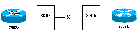
Here is what happens when you pull the transmit fiber strand on the link from SDHb to SDHa:
-
Router 7507a does not receive any keepalives.
-
Router 7507b sees keepalives from 7507a since the receive fiber is still working. Use debug serial interface to confirm this.
Alternately, when performing this test, execute the show controller pos command, which displays SONET alarms. You should see a path alarm indication signal (P-AIS) on router 7507a and a path remote defect indication (P-RDI) on 7507b.
Loopback Tests
If the output of the show interfaces pos command indicates that the serial line is up but the line protocol is down, use loopback tests to determine the source of the problem. Perform a local loop test first, and then a remote test. Refer to Understanding Loopback Modes on Cisco Routers for guidance.
Note: Change the encapsulation from PPP to HDLC when you use loopbacks. The line protocol on an interface configured with PPP comes up only when all LCP and NCP sessions are negotiated successfully.
Line Protocol Status With APS
A POS interface configured for automatic protection switching (APS) brings down the line protocol if the interface is the protect channel and not the working channel. Consider this sample topology:
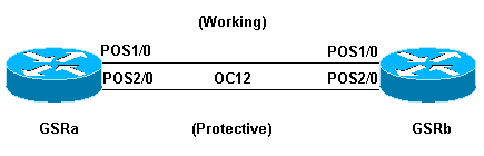
This sample log output was captured after the fiber cabling on GSRb’s POS 1/0 interface was removed. Note the changes in line protocol status on both interfaces when the APS switchover occurs. Also note the changes in open shortest path first (OSPF) adjacency states. (Refer to the APS Technology Support Page for more information.)
*Sep  5 17:41:46: %SONET-4-ALARM:  POS1/0: SLOS
*Sep  5 17:41:46: %SONET-4-ALARM:  POS2/0: APS enabling channel
*Sep  5 17:41:46: %SONET-6-APSREMSWI: POS2/0: Remote APS status now Protect
*Sep  5 17:41:46: %SONET-4-ALARM:  POS1/0: APS disabling channel
*Sep  5 17:41:46: %LINEPROTO-5-UPDOWN: Line protocol on Interface POS2/0,
changed state to up
*Sep  5 17:41:46: %LINEPROTO-5-UPDOWN: Line protocol on Interface POS1/0,
changed state to down
*Sep  5 17:41:48: %LINK-3-UPDOWN: Interface POS1/0, changed state to down
*Sep  5 17:41:48: %OSPF-5-ADJCHG: Process 1, Nbr 192.168.100.100 on POS1/0
from FULL to DOWN, Neighbor Down: Interface down or detached
*Sep  5 17:41:56: %OSPF-5-ADJCHG: Process 1, Nbr 192.168.100.100 on POS2/0
from LOADING to FULL, Loading Done
Avoid configuring APS on a POS interface with PPP encapsulation. PPP is not aware of APS. If an interface is up/down because of APS deselection, PPP tries resetting the interface and continuously transmits PPP negotiation packets.
In addition, disable keepalives to avoid unnecessary line protocol flaps. Keepalives are disabled automatically on most POS router hardware.
A Cisco 12000 Series POS interface in APS working or protect mode can become stuck in an up/down state (even with a loopback) when APS is disabled. Another card inserted in the same slot experiences this problem. Move the card to a new slot to restore proper line-protocol status. This problem is resolved in Cisco IOS Software Release 12.0(19)S under Cisco bug ID CSCdt43759 (registered customers only) .
Use these steps as a workaround:
-
Configure the aps protect command.
-
Issue the aps force 1 command.
-
Configure the no aps protect command.
Known Issues
Note these caveats when you troubleshoot line protocol problems with POS interfaces:
-
A PA-POS interface might reset continuously after the encapsulation is changed from PPP to HDLC. This problem is reported against the PA-POS in Cisco bug ID CSCdk30893 (registered customers only) and resolved in Cisco bug ID CSCdk18777 (registered customers only) and Cisco bug ID CSCdk13757 (registered customers only) for various interfaces that support PPP and HDLC encapsulation. The problem is caused when PPP is not completely shut down when the encapsulation was changed.
-
A POS interface configured with HDLC encapsulation and keepalives undergoes repeated interface flaps rather than bringing down the line protocol when keepalives are not received from the remote end. This problem is resolved in Cisco bug ID CSCdp86387 (registered customers only) .
Related Information
- Optical Technology Support
- Technical Support & Documentation — Cisco Systems
I wonder what can cause that the first line output of the command «show interfaces» will be: «fastEthernet is up, line protocol is down».
Cisco ethernet interfaces are normally down / down if they don’t have a link. If you’re seeing up / down, the most likely causes are:
- Cable fault
- Speed mismatch (I personally haven’t seen a duplex mismatch bring an intf up / down)
- is cable that connected to the local interface, but not connected to the far end switch, will cause that situation?
If the cable is bad…
- is good cable that connected to both switches, but one switch had it’s interface in «administratively down» state, will cause that situation?
I haven’t seen that recently. For example, I have a c3560c in my lab and shutdown fa0/12… then I connected a good cable between the fa0/11 and fa0/12 ports…
sw1#sh ip int brief | i 0/1[1-9]
FastEthernet0/11       unassigned      YES unset  down                  down
FastEthernet0/12       unassigned      YES unset  administratively down down
sw1#
That said, I do have vague memories of seeing up / down when the remote interface was shut on other platforms in the past, but I don’t remember seeing it recently
If the cable is faulty, it could cause up / down status
Testing your cabling:
If you have a Cisco switch, you can test your cabling on the up / down interface like this… the following is good tdr output for the command when nothing is connected to the other end of the cable.
sw1#test cable-diagnostic tdr interface Fa0/6
TDR test started on interface Fa0/6
A TDR test can take a few seconds to run on an interface
Use 'show cable-diagnostics tdr' to read the TDR results.
sw1#
sw1#show cable-diagnostics tdr interface fa0/6
TDR test last run on: February 12 04:45:37

Interface Speed Local pair Pair length        Remote pair Pair status
--------- ----- ---------- ------------------ ----------- --------------------
Fa0/6     auto  Pair A     31   +/- 1  meters N/A         Open
                Pair B     31   +/- 1  meters N/A         Open
                Pair C     N/A                N/A         Not Supported
                Pair D     N/A                N/A         Not Supported
sw1#
Note: FastEthernet interfaces by-definition can only test two of the four pairs. GigabitEthernet interfaces can test all four pairs.
Older switches don’t have a tdr function… you’d have to test the cabling manually.
Greetings,
I had a class B VLan of 172.18.0.0/255.255.0.0
I wanted to carve it up a bit. SO I went with 172.18.0..1/255.255.254.0
as well as another vlan 172.18.2.0/255.255.254.0
I’m on a cisco cat 6509. I still have other vlans of a wide open class b such as 172.16.0.0/255.255.0.0 and 172.17.0.0/255.255.0.0
So here’s what I typed..
no interface vlan 18 (killed off the old huge vlan)
int vlan 181 ip address 172.18.0.1 255.255.254.0
int vlan 182 ip address 172.18.2.1 255.255.254.0
So when I do a int vlan 181 (or) 182 NO SHUTDOWN I don’t get a warning
then show int vlan 182 or 181 and I get
Vlan181 or 182 is down, line protocol is down
I cannot get these new vlans up.
Please note: there are other class b vlans in play still. Would this booger anything up on me?
UPDATE: I decided to delte the newly created vlans and start from square 1 again. recreated the huge old vlan 18 172.18.200.1 255.255.0.0 now THAT’s not coming up either.
Наверное, каждому из читателей, встречавшемуся с устройствами фирмы Cisco, доводилось выполнять на них команду show interfaces … Сегодня мы немного поковыряемся в выводе данной команды и разберем возможные состояния интерфейсов и протоколов линии(line protocol).
Для начало разберемся с тем , что такое состояние интерфейса и что такое состояние протокола линии. Состояние интерфейса, грубо говоря, сигнализирует о состоянии работы интерфейса нашего устройства на физическом уровне, состояние протокола линии обычно сигнализирует о состоянии работы данного интерфейса на канальном уровне. Данные состояния выводятся вместе при выполнении команд show interfaces на устройствах фирмы Cisco и имеют следующий вид (первая часть вывода свидетельствует о состоянии интерфейса, вторая, как легко догадаться, о состоянии протокола линии):
FastEthernet0/1 is up, line protocol is up (connected)
Рассмотрим, какие пары значений могут принимать данные состояния:
Состояние интерфейса – UP, состояние протокола линии – UP:
Думаю именно это состояние желает увидеть каждый сетевик, выполняя на циске команду show interfaces, так как именно оно свидетельствует о том, что интерфейс работает нормально.
Проиллюстрируем данную ситуацию в Packet Tracer. Соберем следующую схему:
 |
| Воспроизводим ситуацию Интерфейс — UP, протокол — UP |
Потом, выполним на коммутаторе следующую команду:
Switch#show interfaces fastEthernet 0/1
Часть её результата будет такова:
FastEthernet0/1 is up, line protocol is up (connected)
Hardware is Lance, address is 00d0.ffd8.7701 (bia 00d0.ffd8.7701)
……………………………………………………
Как можно заметить в данной ситуации интерфейс работает нормально и имеет состояния UP как на интерфейсе, так и на протоколе линии.
Состояние интерфейса – Administratively Down, состояние протокола линии – Down:
Данное состояние можно наблюдать на устройствах фирмы Cisco, в том случае если используемый порт был административно отключен с помощью команды shutdown. Продемонстрируем данный случай, для этого выполним на схеме из предыдущего примера следующие команды:
Switch(config)#interface fastEthernet 0/1
Switch(config-if)#shutdown
После чего опять посмотрим состояния интерфейса:
FastEthernet0/1 is administratively down, line protocol is down (disabled)
Hardware is Lance, address is 00d0.ffd8.7701 (bia 00d0.ffd8.7701)
……………………………………………………
Как и ожидалось интерфейс административно отключен.
Состояние интерфейса – Down, состояние протокола линии – Down(Err—disabled):
Такое состояние обычно встречается в том случае если на порте были произведены настройки безопасности для определенного mac адреса (подключиться к данному порту можно только с определенных mac адресов), а к нему подключились с устройства имеющего другой mac адрес.
Продемонстрируем данный случай. Будем использовать схему из предыдущих примеров, но коммутатор сконфигурируем следующим образом.
Switch(config)#interface fastEthernet 0/1
Switch(config-if)#switchport mode access
Switch(config-if)#switchport port-security
Switch(config-if)#switchport port-security violation shut
Switch(config-if)#switchport port-security mac-address 00E0.F795.C477
Switch(config-if)#exit
Switch(config)#interface vlan 1
Switch(config-if)#ip address 1.1.1.1 255.255.255.0
Switch(config-if)#no shut
После этого подключим к порту коммутатора компьютер имеющий адрес 1.1.1.2 c маской 255.255.255.0 и MAC адресом 00E0.F795.C472. После чего попробуем с компьютера пропиговать наш коммутатор. Как вы можете заметить пинги не прошли, а порт коммутатора заблокировался. Теперь попробуем посмотреть, что нам выдаст show interfaces fastEthernet 0/1.
FastEthernet0/1 is down, line protocol is down (err—disabled)
Hardware is Lance, address is 00d0.ffd8.7701 (bia 00d0.ffd8.7701)
……………………………………………………
По данному результату можно посмотреть состояния интерфейса при блокировки порта настройками безопасности.
Состояние интерфейса – Down, состояние протокола линии – Down:
Такое состояние может наблюдаться в том случае если к порту ничего не подключено, или же подключено но с помощью неисправного кабеля. Думаю что данная ситуация не нуждается в демонстрации =).
Состояние интерфейса – UP, состояние протокола линии – Down:
Честно говоря такую комбинацию состояний довольно трудно встретить в локальных сетях построенных на Ethernet коммутаторах, но она может возникнуть на интерфейсах маршрутизаторов, использующих последовательные каналы, при несогласовании протоколов канального уровня.
Рассмотрим это на следующем примере. Соберем в Cisco Packet Tracer следующую схему (в каждый маршрутизатор установлено по плате WIC-1T, порты которых соединены между собой):
 |
| Воспроизводим ситуацию Интерфейс — UP, протокол — Down |
Сконфигурируем один из маршрутизаторов следующим образом:
Router(config)#interface Serial0/3/0
Router(config-if) ip address 1.1.1.1 255.255.255.0
Router(config-if) encapsulation ppp
Router(config-if) clock rate 64000
Router(config-if)no shut
А другой:
Router(config)#interface Serial0/3/0
Router(config-if) ip address 1.1.1.2 255.255.255.0
Router(config-if) encapsulation hdlc
Router(config-if)no shut
Если после применения данной конфигурации вы попробуете пропинговать с одно маршрутизатора другой, то у вас ничего не выйдет. Дело в том что в данных конфигурациях для соединенных интерфейсов мы указали разные протоколы канального уровня. И как следствие связь не была установлена. Если же мы теперь выполним команду show interfaces serial 0/3/0 на одном из маршрутизаторов, то получим вполне предсказуемый результат:
Serial0/3/0 is up, line protocol is down (disabled)
Hardware is HD64570
Internet address is 1.1.1.1/24
MTU 1500 bytes, BW 128 Kbit, DLY 20000 usec,
……………………………………………………
Состояние интерфейса – Down, состояние протокола линии – UP:
Как легко догадаться такой комбинации состояний не существует. Так как если связь на физическом уровне не осуществляется, то о связи на канальном уровне не может быть и речи.
Пока что это все.
P.S.
В статье использовались материалы из книги Уэнделл Одом «Официальное руководство Cisco по подготовке к сертификационным экзаменам CCENT/CCNA ICND1 640-822″
Protocol Status refers generally two the layer to status. It is always down if the Line status is down. if the Line status is up,a protocol status of down usually is caused by mismatched data link layer configuration
For an example serial interfaces has their combination when one router has configured to use PPP(Point_to_Point Protocol) and other remains the default HDLC (Higher_level Data Link Control) configuration and this will cause to display as «Line status Up Protocol Down» .
- Before Configure one router to PPP (Default is HDLC)
R1#show interfaces serial 1/0
Serial1/0 is up, line protocol is up (connected)
Hardware is HD64570
MTU 1500 bytes, BW 128 Kbit, DLY 20000 usec,
reliability 255/255, txload 1/255, rxload 1/255
Encapsulation HDLC, loopback not set, keepalive set (10 sec)
R2#show interfaces se1/0
****Serial1/0 is up, line protocol is up** (connected)**
Hardware is HD64570
MTU 1500 bytes, BW 128 Kbit, DLY 20000 usec,
reliability 255/255, txload 1/255, rxload 1/255
Encapsulation HDLC, loopback not set, keepalive set (10 sec)
- After configuring R1 as PPP
R1#show interfaces serial 1/0
Serial1/0 is up, line protocol is down (disabled)
Hardware is HD64570
MTU 1500 bytes, BW 128 Kbit, DLY 20000 usec,
reliability 255/255, txload 1/255, rxload 1/255
Encapsulation PPP, loopback not set, keepalive set (10 sec)
R2#show interfaces serial 1/0
Serial1/0 is up, line protocol is down (disabled)
Hardware is HD64570
MTU 1500 bytes, BW 128 Kbit, DLY 20000 usec,
reliability 255/255, txload 1/255, rxload 1/255
Encapsulation HDLC, loopback not set, keepalive set (10 sec)