В этой статье рассмотрим основные электронные элементы для построения электрических схем в программе Proteus и как их найти в библиотеке компонентов.
Где искать элементы в протеусе?
Для того, чтобы добавить элемент в протеусе на рабочую область необходимо перейти в компонентный режим, нажав на иконку операционного усилителя ![]() , а после нажать на иконку с буквой P (Pick devices) —
, а после нажать на иконку с буквой P (Pick devices) — ![]() .
.

После чего откроется окно для поиска нужного электронного элемента. Поиск можно произвести по ключевой фразе или поиском в определенной категории. Если нужно быстро создать схему для симуляции, то лучше воспользоваться поиском по ключевой фразе. Дальше мы перечислим основные элементы и ключевые фразы для них.

Базовые элементы
Постоянный резистор
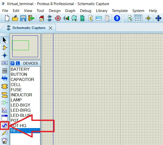
Чтобы найти обычный постоянный резистор в программе Proteus, вводим ключевую фразу RES и получаем единственный результат, который вполне нас устроит.

Выбираем его, нажимаем кнопку OK и кликаем два раза на рабочую область левой кнопкой мыши для добавления элемента.
Если нажать на только что вставленный резистор два раза, то откроется окно свойств элемента.

Здесь мы можем изменить обозначение на схеме в поле Part Reference (например, R1 изменить на R8).
В поле Resistance указываем сопротивление резистора: укажем просто 100 — будет 100 Ом, 470k — 470 килоОм, 2.2M — 2.2 МегаОма.
Если установим галочку Hidden, то на схеме это свойство отображаться не будет.
Не забываем нажимать кнопку OK для сохранения значений.
Переменный резистор
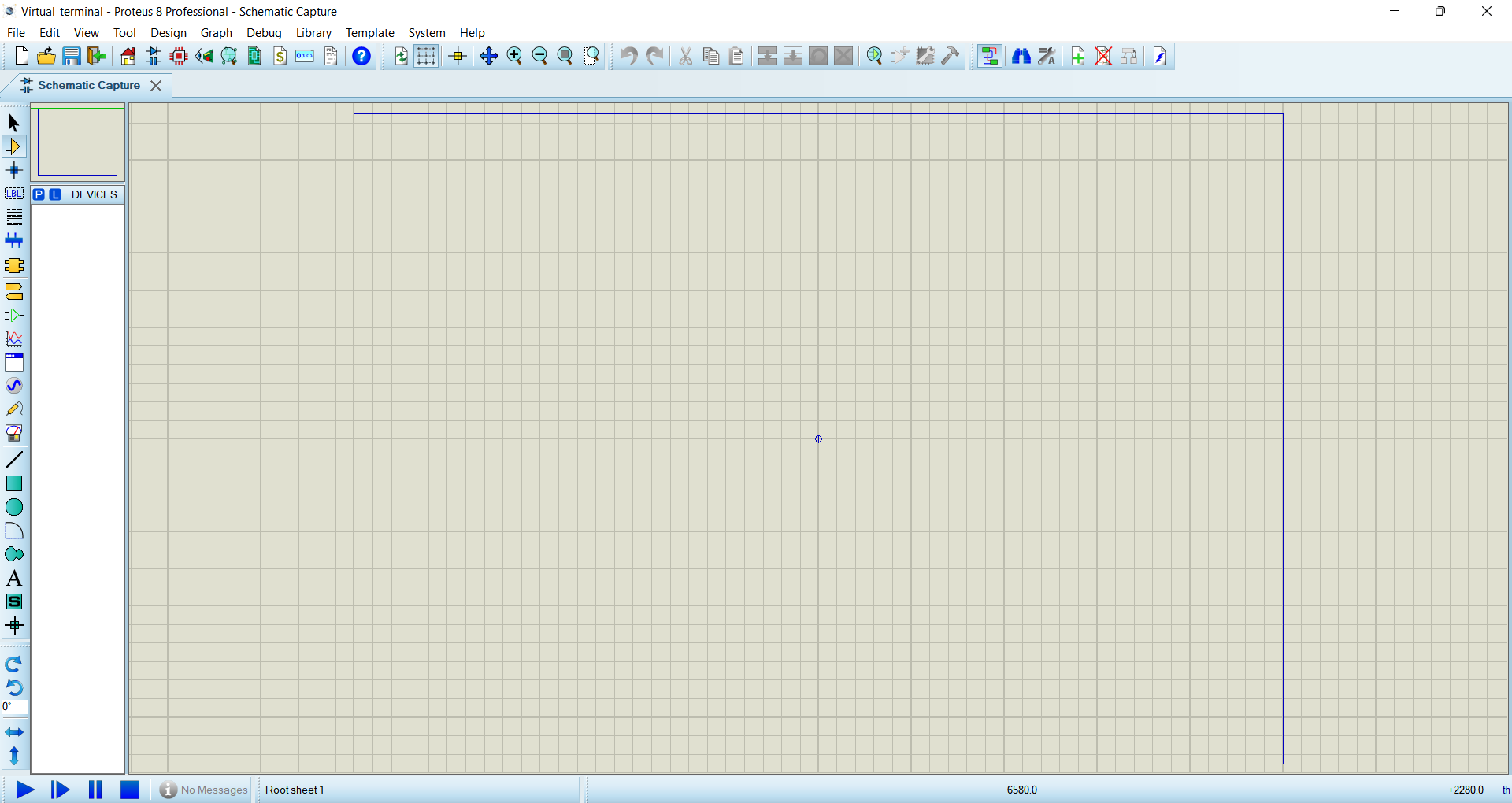
Переменный резистор можно найти под названием POT-HG. Если его добавить на схему, то можно увидеть стрелки вверх и вниз, которыми можно изменять значение сопротивления во время моделирования схемы.

Немного о свойствах потенциометра. Как и у обычного резистора, Part Reference — обозначение на схеме, а Resistance — сопротивление.
Здесь стоит отметить свойство Law Type — по какому закону будет изменяться сопротивление:
- LINEAR — линейный закон;
- LOG — логорифмический закон;
- ANTILOG — обратный логорифмический закон.
Конденсатор
Чтобы было видно при моделировании работы схемы, как накапливается заряд на обкладках конденсатора, нужно использовать модель под именем CAPACITOR из библиотеки ACTIVE.

Свойства конденсатора: Part Reference — обозначение на схеме; Capacitance— емкость, указывается с приставками: 1m — 1 миллиФарад, 47u — 47 микроФарад, 100n — 100 наноФрарад, 10p — 10 пикоФарад; Working Voltage — рабочее напряжение.

Катушка индуктивности
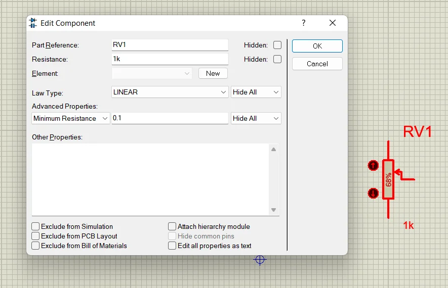
Катушку индуктивности в протеусе можно найти по ключевой фразе INDUCTOR.

Чтобы установить необходимую индуктивность катушки, нажимаем два раза на элемент левой кнопкой мыши или нажимаем правой кнопкой мыши на элемент и выбираем в всплывающем меню пункт Edit Properties, затем в поле Inductance устанавливаем необходимое значение: например, 1mH — один миллиГенри, 330uH — 330 микроГенри и т.д.
Светодиод
Ну как же мы можем обойтись без этого элемента?! Да никак! Вот эти светодиоды из библиотеки, которые поддерживают анимацию: синий цвет: LED-BLUE, зеленый цвет — LED-GREEN, красный цвет — LED-RED, желтый цвет — LED-YELLOW.

Кроме этого, есть еще двухцветные светодиоды: LED-BIBY — сине-желтый светодиод, LED-BIGY — зелено-желтый светодиод, LED-BIRG — красно-зеленый светодиод, LED-BIRY — красно-желтый светодиод. Для того, чтобы изменить цвет, необходимо изменить полярность на противоположное.
Про то, как добавить библиотеку RGB-светодиода в Proteus можете прочитать здесь.
Из интересующих свойств элемента сейчас можно выделить: прямое напряжения светодиода — Forward Voltage, прямой ток — Full drive current, напряжение пробоя — Breakdown Voltage.

Кнопка и переключатель
Еще один не маловажный элемент в электрической схеме — кнопка. Обзывается она в протеусовской библиотеке как BUTTON.

Для схожих целей (замыкать и размыкать цепь) служит и переключатель. Его можно найти под названием SWITCH. В библиотеке можно найти и другие виды переключателей.
О видах переключателей Вы можете узнать из этой статьи.

Лампочка
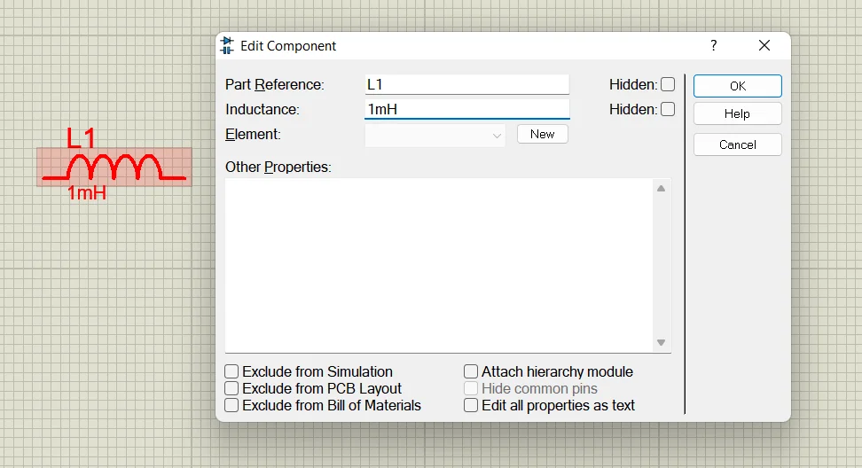
Лампочку с анимацией можно найти по ключевому слову LAMP.

У лампочки имеется два важных свойства:
- Nominal Voltage — рабочее напряжение лампы;
- Resistance — сопротивление лампы.
Предохранитель
Классная защитная штука, которая обрывается при превышении определенного значения проходящего через него тока. Этот элемент с анимацией можно найти по ключевому слову FUSE из библиотеки ACTIVE.

Свойства предохранителя в протеусе:
- Rated Current — номинальный ток, после превышения этого значения происходит обрыв предохранителя;
- Resistance — вносимое сопротивление в цепь предохранителем.

Питание и земля
Выводы источника питания и земли
Чтобы добавить источник питания (Vcc) и землю (GND) в программе Proteus, перейдите в режим Terminals Mode, нажав на иконку ![]() . Вам будет доступно 8 вводов/выводов, из которых сейчас нам интересны POWER — питание и GROUND — земля.
. Вам будет доступно 8 вводов/выводов, из которых сейчас нам интересны POWER — питание и GROUND — земля.
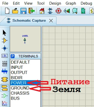
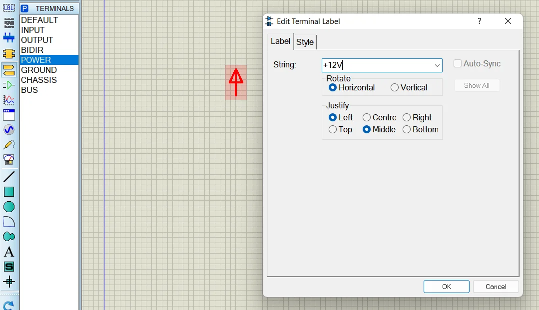
Чтобы установить необходимое постоянное напряжение, зайдите в свойство элемента POWER и в поле String введите нужное значение: например, +12V, -5V и т.д., после чего нажмите кнопку OK.
Генерация постоянного напряжения
Рассмотрим еще один способ «запитать» схему постоянным напряжением. Перейдите в режим генераторов, нажав на иконку ![]() .
.
И добавьте DC генератор на рабочую область. Теперь зайдите в его свойства, нажав по нему два раза левой кнопкой мыши, и в поле Voltage (Volts) введите напряжение питания схемы в вольтах.

Аккумуляторная батарея
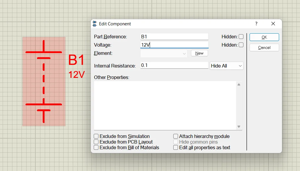
Еще одним вариантом подать питание на схему — это использовать батарею. Этот элемент можно найти по ключевому слову BATTERY.

В свойствах мы можем указать напряжение батареи в поле Voltage.
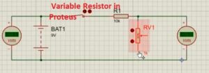 Hello, readers welcome to the new post. Here we will learn How To Use Variable Resistors in Proteus. Resistance is the very basic part of any circuit that can create a hindrance in the flow of current in the circuitry. each material has a certain value of resistance and resistance or ohmmeter is used for finding the value of resistance offered by the circuitry.
The formula of resistance is R=ΡL/α. Resistance is a term used in the electrical system to explain the opposition that occurs in the flow of current. In this post, we will make a circuit and see the practical understanding of the variable resistance used in the circuit and learn its proteus simulation.
Introduction to Variable Resistor
- The variable resistor is a category of resistor that has the ability to change tis resistance measuring capacity.
- It is an electromechanical device that consists of a slider having resistance components to vary the resistance.
- If it is linked in such a way that there is a larger resistance is given then less value of current passes and in case of a small value of resistance high current passes.
- Through varying, the resistance of circuitry can also be used as a volts control device of any circuit.
- It is called a potentiometer when working as a voltage or potential divider.
- When working as a variable resistor called a rheostat.
- There is a certain type of variable resistance that operates electronically way named a digital potentiometer.
Variable Resistor Features
- Its main features are listed here
- The physical dimensions of this resistance is large then other resistance commonly used
- It consists of three terminals first one is moveable pinout and other 2 are not moveable
- It comes with the changeable port.
- It is used in small level signal circuits.
- To learn the understanding of the variable resistor in proteus we will make a circuit and use the variable resistance in the proteus practically.
- First of all open the proteus on your PC then move to component library and choose the component of projects that are listed here.
- Battery
- Resistance
- Voltmeter
- Switch
- Variable Resistance
- All components are can seen here
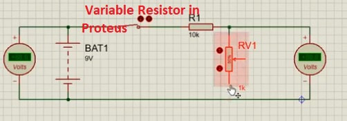
- Make the circuit according to shown diagram and link all elements in a proper way as required.
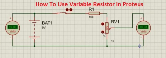
- When you make the circuit run the simulation and see the results at the output voltmeter.
- Then vary the value of variable resistance through pressing on the point of the resistor in a result you will see the variation in the value of output voltages at the voltmeter.
- Can be easily seen that with the change in the resistance value of volts varying.
Applications Variable Resistance
- They are used to control the speed of DC motors. Since they provide flexible resistance, it varies current and voltage. The speed can therefore be easily controlled by system or armature voltage control.
- They are used in indoor applications such as changing the speed of ceiling fans. Nothing but a simple potentiometer.
- They are often used in laboratories in educational institutions and research units to conduct tests.
- Other common applications for potentiometers, sound control, lighting, etc. Also used for microphones and audio systems to adjust the volume.
- Digital Rheostats has a number of applications. They are embedded as circles attached to a printed circuit board. They can be connected to signal processors to control electronic resistance.
Set-up rheostats have low specific applications such as radio, transmission circuits, etc.
That is all about the How To Use Variable Resistor in Proteus if you have any further query ask in the comments. Thanks for reading have a good day see you in next post.
Author: Henry
http://www.theengineeringknowledge.com
I am a professional engineer and graduate from a reputed engineering university also have experience of working as an engineer in different famous industries. I am also a technical content writer my hobby is to explore new things and share with the world. Through this platform, I am also sharing my professional and technical knowledge to engineering students.
 Поговорим о такой замечательной программе для симуляции электронных схем как Proteus 7, (а конкретнее версия 7.10). Для начала что такое симулятор, и зачем он нужен. Симулятор электронных схем Proteus 7, предназначен для моделирования составленных вами электронных схем. То есть вы рисуете схему (добавляете нужные компоненты и соединяете в нужной последовательности), а затем добавляете измерительные приборы, которые вам нужны для контроля работоспособности. Вся прелесть в том что в железе ничего собирать не нужно. Накидал схему и смотришь как она работает, измеряешь ее параметры. Иногда, конечно, случается что в железе все работает по другому. Вообще для Proteus 7 нужен компьютер по мощнее. Теперь познакомимся с самой программой. Запускаем программу и после загрузки видим: рабочее поле, панели инструментов (расположены вверху и слева), и панель свойств.
 Создадим простой проект. Добавим светодиод, резистор, кнопку, питание и соединим все это, чтобы при нажатии на кнопку светодиод горел. Нажимаем «Компоненты», на панели свойств нажимаем «P».
 Можно искать через категории нужный нам компонент, ну а можно и просто по названию. В строке поиска пишем «LED» и выбираем светодиод, например синий. Щелкаем по нему 2 раза и он добавляется в наши компоненты. Также добавим кнопку и резистор.
 Теперь в нашей панели есть светодиод, кнопка и резистор. Выделяем первый компонент и делаем один клик на рабочем поле. Компонент добавлен. Размещаем компоненты как удобно. Для резистора нужно задать номинал. Для этого щелкаем по нему 2 раза и в окне свойств вводим нужный нам номинал.
 Теперь их нужно соединить. Для этого наводим курсор на один из выводов и делаем клик левой кнопкой мыши, и ведем проводник к подключаемому выводу и снова кликаем.

Теперь нужно добавить питание. Жмем на кнопку «Terminal» и добавляем элементы Power (+) и Ground (-).
 Напряжение по умолчанию здесь 5В. (добавляются на рабочее поле они точно так же как и компоненты). И соединяем их с нужными точками схемы. В итоге получается такая схема.
 Теперь смотрим в нижнем левом углу панель запуска симуляции. Все, как и в проигрывателе, треугольник — старт, квадрат — стоп ну и т.д. Запускаем, наводим курсор на кнопку и нажимаем ее.
 Убеждаемся что светодиод горит.
 Теперь останавливаем симуляцию. Если этот проект потребуется в будущем, можем его сохранить через меню Файл->Сохранить.
В следующей статье поговорим об измерительных приборах которые доступны для моделирования.
СКАЧАТЬ PROTEUS 7.10 SP0 RUS & CRACK
Форум РадиоКот • Просмотр темы — Proteus: вопросы и ответы
Сообщения без ответов | Активные темы
| ПРЯМО СЕЙЧАС: |
| Автор | Сообщение |
|---|---|
|
|
Заголовок сообщения: Re: Proteus: вопросы и ответы
|
|
Друг Кота
Карма: 33 Рейтинг сообщения: 0
|
Aid1992 писал(а): Ну а где я могу найти датчик MQ-4? Тоже хочу нарисовать схемку в Proteus. Нарисуйте, для этого в Proteus все есть. |
| Вернуться наверх |
Профиль
|

| Реклама | |
|
|
|
|
Aid1992 |
Заголовок сообщения: Re: Proteus: вопросы и ответы
|
||
Зарегистрирован: Вс ноя 11, 2012 14:13:02 Рейтинг сообщения: 0
|
Soir писал(а): Нарисуйте, для этого в Proteus все есть. Ок. Спасибо что помогли. |
||
| Вернуться наверх | |||

| Реклама | |
|
|
|

|
Soir |
Заголовок сообщения: Re: Proteus: вопросы и ответы
|
||
|
Карма: 33 Рейтинг сообщения: 0
|
Aid1992 писал(а): Ок. Спасибо что помогли. Не за что. Такой рисунок делается за 3 минуты, но для создания модели требуется больше времени и знаний. Снова хочется вспомнить про FAQ на казусе.
|
||
| Вернуться наверх | |||
|
Chettuser |
Заголовок сообщения: Re: Proteus: вопросы и ответы
|
|
|
Не за что! |
| Вернуться наверх | |
| Реклама | |
|
|
ИБП MEAN WELL серии DRC-180 на DIN-рейку – новое решение для пожарно-охранных систем
Компания MEAN WELL расширила семейство DRC-40/60/100 – недорогих ИБП (UPS) 2-в-1 (ИП и контроллер заряда/разряда АКБ в одном корпусе) с креплением на DIN-рейку. Теперь доступны модели мощностью 180 Вт новой серии DRC-180. Подробнее>> |
|
radio-kot |
Заголовок сообщения: Re: Proteus: вопросы и ответы
|
||
Карма: -22 Рейтинг сообщения: 0
|
у того кто схему в проте рисовал |
||
| Вернуться наверх | |||

| Реклама | |
|
|
|
| Реклама | |
|
|
Выбираем источники питания MEAN WELL в открытом исполнении для промышленных устройств В номенклатуре продукции MEAN WELL в Компэл можно легко найти требуемую модель стандартного источника питания практически для всех отраслей применения. Рассмотрим преимущества, эксплуатационные характеристики, схемотехнику и конструктивные решения трех наиболее характерных представителей класса источников питания в открытом исполнении семейств EPS, EPP и RPS, которые могут использоваться для индустриальных устройств. Подробнее>> |
|
alex1126 |
Заголовок сообщения: Re: Proteus: вопросы и ответы
|
|
Зарегистрирован: Ср дек 19, 2012 12:16:22 Рейтинг сообщения: 0
|
А можно как-нить вывести список всех элементов которые на схеме с их номиналами? |
| Вернуться наверх | |
|
Soir |
Заголовок сообщения: Re: Proteus: вопросы и ответы
|
|
Карма: 33 Рейтинг сообщения: 0
|
alex1126 писал(а): А можно как-нить вывести список всех элементов которые на схеме с их номиналами? Можно. Alt+X или Design -> Design Explorer. |
| Вернуться наверх | |
|
alex1126 |
Заголовок сообщения: Re: Proteus: вопросы и ответы
|
|
Зарегистрирован: Ср дек 19, 2012 12:16:22 Рейтинг сообщения: 0
|
Soir писал(а): alex1126 писал(а): А можно как-нить вывести список всех элементов которые на схеме с их номиналами? Можно. Alt+X или Design -> Design Explorer. а в более удобоваримом виде можно этот список получить? Ну хотя бы вставить на лист с проектом. Нужно что бы распечатать список необходимых деталей…. |
| Вернуться наверх | |
|
alex1126 |
Заголовок сообщения: Re: Proteus: вопросы и ответы
|
|
Зарегистрирован: Ср дек 19, 2012 12:16:22 Рейтинг сообщения: 0
|
Набросал схему с L297 и L298/ Все по даташиту. Вложение:
Но при этом вылетают ошибки что некоторые пины не смоделированы… Вложение:
Вроде все работает при этом… что не так? |
| Вернуться наверх | |
|
Murka |
Заголовок сообщения: Re: Proteus: вопросы и ответы
|
||
Карма: 12 Рейтинг сообщения: 0
|
alex1126 писал(а): А можно как-нить вывести список всех элементов которые на схеме с их номиналами? Вложение:
|
||
| Вернуться наверх | |||

|
alex1126 |
Заголовок сообщения: Re: Proteus: вопросы и ответы
|
|
Зарегистрирован: Ср дек 19, 2012 12:16:22 Рейтинг сообщения: 0
|
Murka писал(а): супер. спасибо, то что надо. С кол-вом, сгруппированы. |
| Вернуться наверх | |
|
passer_by |
Заголовок сообщения: Re: Proteus: вопросы и ответы
|
||
Зарегистрирован: Сб янв 05, 2013 21:03:05 Рейтинг сообщения: 0
|
alex1126 писал(а): Набросал схему с L297 и L298/ Все по даташиту. Proteus по моему VREF, OSC не моделирует. Их можно и не подключать. А вот в живую, подключение VREF на +5v приведет к отключению защиты L298. А ругается Proteus скорее всего на странные значения резисторов R3, R6 — «0R1». Сопротивление не может быть равным 0 и что за размерность «R1»? |
||
| Вернуться наверх | |||

|
Murka |
Заголовок сообщения: Re: Proteus: вопросы и ответы
|
||
Карма: 12 Рейтинг сообщения: 0
|
passer_by писал(а): странные значения резисторов R3, R6 — «0R1». Сопротивление не может быть равным 0 и что за размерность «R1»? 0.1 Ом, Буква ставится вместо запятой. |
||
| Вернуться наверх | |||
|
alex1126 |
Заголовок сообщения: Re: Proteus: вопросы и ответы
|
|
Зарегистрирован: Ср дек 19, 2012 12:16:22 Рейтинг сообщения: 0
|
passer_by писал(а): alex1126 писал(а): Набросал схему с L297 и L298/ Все по даташиту. Proteus по моему VREF, OSC не моделирует. т.е. все нормально? Забить на варнинги? Цитата: Их можно и не подключать. А вот в живую, подключение VREF на +5v приведет к отключению защиты L298. Это я знаю. А соколько туда пускать лучше? Цитата: А ругается Proteus скорее всего на странные значения резисторов R3, R6 — «0R1». Сопротивление не может быть равным 0 и что за размерность «R1»? Ну во первых, как правильно уже заметили, это нормальное обозначение номинала резистора. Во вторых этот резистор взят из библиотеки протеуса. Не абстрактный резистор, а конкретный, с размерами… ну что бы развести плату потом сразу. |
| Вернуться наверх | |
|
shads |
Заголовок сообщения: Re: Proteus: вопросы и ответы
|
||||
Карма: 8 Рейтинг сообщения: 0
|
Подскажите, кто сталкивался…. Эмулирует ли прот выводы ADC6 и ADC7 у меги8 ?
|
||||
| Вернуться наверх | |||||


|
Orion33 |
Заголовок сообщения: Re: Proteus: вопросы и ответы
|
|
Карма: -25 Рейтинг сообщения: 0
|
У меня работает, я 7й канал использовал для инициализации записи в ЕЕПРОМ после отключения питания. Правда, модель я брал 88ю. Вроде как 8ю на 88ю можно заменять без проблем. |
| Вернуться наверх | |
|
Engineer_Keen |
Заголовок сообщения: Re: Proteus: вопросы и ответы
|
||
Карма: 32 Рейтинг сообщения: 0
|
AREF и AVCC в воздухе висят??? |
||
| Вернуться наверх | |||

|
shads |
Заголовок сообщения: Re: Proteus: вопросы и ответы
|
||
Карма: 8 Рейтинг сообщения: 0
|
Engineer_Keen писал(а): AREF и AVCC в воздухе висят??? Оо…. спасибо. |
||
| Вернуться наверх | |||
|
Engineer_Keen |
Заголовок сообщения: Re: Proteus: вопросы и ответы
|
||
Карма: 32 Рейтинг сообщения: 0
|
Обычно протеус сам ругается когда АЦП используется при не подключенном AREF… |
||
| Вернуться наверх | |||
|
shads |
Заголовок сообщения: Re: Proteus: вопросы и ответы
|
||
Карма: 8 Рейтинг сообщения: 0
|
Engineer_Keen писал(а): Обычно протеус сам ругается когда АЦП используется при не подключенном AREF… Действительно ругается….. (только сейчас заметил) В общем спасибо огромное! |
||
| Вернуться наверх | |||
Кто сейчас на форуме |
|
Сейчас этот форум просматривают: нет зарегистрированных пользователей и гости: 11 |
| Вы не можете начинать темы Вы не можете отвечать на сообщения Вы не можете редактировать свои сообщения Вы не можете удалять свои сообщения Вы не можете добавлять вложения |

Introduction: Simulating Designing of Circuits+PCB on Proteus
This is a step by step instructable for Engineers and hobbyist. In this instructable I will discuss about circuit simulations & PCB designing on Proteus 8, at the end I will also discuss about etching of electric circuits within 5 minutes.
With the help of this instructable you can make single layer auto+manual routing double layer auto and manual PCB routing. You would be able to make very small size PCB of large circuits.
Step 1: Installing Proteus 8.0
You can install from labcentre or you can visit the following link in this link and you can watch a tutorial video about how to download Proteus 8 or any other version of Proteus.
LINK
Step 2: Getting Started
When you launch Prteus click on New Project or press CTRL+N. A new window called New Project Wizard appears
- Start
There you can change the Name and Path of the project after setting click Next
- Schematic Design
Now you need to Mark Create a schematic from the selected template then you can either select Default or you can select any templates size normally we select landscape A4, by selecting the Landscape A4 you will have a schematic window as shown in the picture 4
- PCB Layout
If you do not want PCB design just click Next otherwise Mark on create a schematic from the selected template, now you can select Generic single layer or any other layer of your requirement and then click Next, by selecting single layerif you do auto-routing then the software will do only single layer routing(bottom) if you select default and then upon selecting auto-routing the software would double layer(top & bottom layer routing).
- Firmware
Normally we select No firmware Project, but if we require to work with microcontrollers like 8051, Arduino we select Creat Firmware Project, and select the options accordingly, if anybody wants to know about that just write down a comment, I would guide for that.
- Summary
Here you can check the selected options and click Finish.
Step 3: Placing the Components
A black colored window would appear that is PCB layout tab, you can switch the tab to schematic capture
Click on P button it stands for place, a new window would appear, In this window you can search for the components by typing exact names like 1n4007(diode) or simply type diode but if you want to make PCB you have to check that your selected component has a PCB design which is shown in PCB preview. Double click the required component and it would appear in your devices and search for other components and place them all in your devices section, some of the components might not have the PCB previews but we can add the PCB layout of them(mentioned later).
Tips:
- for electrolytic capacitors just tzpe cap-elec
- for ceramic capacitor type cap
- for resistor type res
- for AC source type VSINE
Sometimes you may have different package but you are selecting another component you need to select appropriate PCB as described here for potentiometer(variable resistor) there are many kinds of potentiometer available in market so you need to first check what is available for your then you can select appropriate design, I have mentioned here some of the potentiometers.
Step 4: Making the Schemetic
for this tutorial I designed a Variable Power Supply
- Make sure you selected the little diode button
- select any component as I clicked 1n4007 from devices section by clicking them once, then click in the area provided for drawing the circuit now the component is available to be place anyzhere, to place click again. If you want another 1N4007 just click again as many times as you want. similarly place all the components
- to join the components with each other click on one end of a component, a line would start, you can click on the other components where you want it to join like in the picture. similarly complete your circuit diagram.
- To change the values of components(resistors, capacitors) double click on the component and change it.
- Similarly change the value of VSINE by double clicking it. As it is AC you need to add frequency and voltage value as mentioned at output terminals of transformer.
- To add a voltmeter click on the meter icon and select DC VOLTMETER then click where ever you want to place it connect it by wires(lines) if necessary
- To check the circuit click on the play icon on bottom left of the proteus.
- I have attached last two pictures by changing the value of variable resistor check the output voltage.
- At this step we have simulated our circuit and verified it on Proteus you need to save this file for later purposes
Step 5: Preparation for PCB Design
As you know we can not place VSINE or Transformer on the PCB board we need to add a block which is called as TBLOCK-I2 it is a two terminal connector at which we will connect our output terminals of the transformer similarly for the voltmeter we are going to put the same terminal block.
For this purpose we will replace VSINE and voltmeter with terminal block (TBLOCK)
Now only remaining component is LED who’s PCB footprint is missing so we need to add the PCB footprint of LED for that purpose double click the LED click on the question mark a new window named packages would appear type LED and double-click LED now and the PCB package you can see there would be written LED at the end.
You can rename the terminal blocks by input and output or whatever you like
The schematic is ready for PCB designing
Step 6: PCB Desiging
Board Edge (Border or Size)
- Click on the PCB layout tab then zoom in to upper left corner as shown in pictures this block is 1×1 cm in area
- Now from the left toolbar click on the Square button and from the bottom toolbar select Board Edge.
- Draw a rectangle of any size by clicking anywhere inside the blue area of the PCB window, as you can see I have drawn a 2 x 2 cm² block. This is the size of your PCB you can change it by hoovering your mouse pointer at any corner off this Block. As I have also changed it after completing the design.
- Now click on the small diode icon which indicate that component lists. Select the component and then click inside the yellow Square to place it
- When you would be placing a component you will see green lines which indicates the connection of one point to the other point and the Yellow arrow head which indicates that this component is to join with this terminal of the other component. Place the components wherever you like keep in mind that you choose simple and easy path which is indicated by the green lines. After placing all the components you can adjust the yellow rectangle
- Make sure there are no DRC errors on the bottom status bar, DRC error appears when there is an overlapping of a terminal with other terminals or with board edge.
Auto-Routing
- Click on the routing button from left toolbar as described in picture then double click default, change the default width to 20th or 25th (this is the thickness of your PCB routing) and click OK
- Now click on the second last icon (Auto-Router) and check the Wire-Grid and Via-Grid it should be more than 15 other wise soldering would be difficult in close connections. then click Begin Routing
- After routing make sure there are no CRC errors, in case there is an error there would be a connection missing press CTRL+Z and re-arrange that component and start routing again.
Manual-Routing
- Click on the routing button from left toolbar as described in picture then double click default, change the default width to 20th or 25th (this is the thickness of your PCB routing) and click OK
- Click on any terminal the point that terminal wants to connect would be highlighted just click on that highlighted terminal same as we did while making the schematic. Make all the connections you would notice that whenever you are making the connection the CRC errors would be reduced after all the connections there would be no CRC error.
Note : After Routing (Auto or Manual) just make sure there are no errors
Additional Step
If you want to make your PCB design more professional click on tools then the second last item name power plan generator Just click ok and see what happens with your PCB design
Step 7: 3D View
Proteus offer to students a 3D visualisation tool you can see your circuit in 3D which is quite awesome
Step 8: Printing Out PCB for Etching (Toner Transfer Method)
For etching you need to print the PCB layout on a glossy sheet from a laser printer
For printing the PCB layout there are two methods
- Go to output click on export graphics then click on export Adobe PDF file in this method you will save the PCB layout as a PDF file and dialog box will open from this box only select the bottom copper and the Board Edge and un-check everything else and click OK. You need to check the actual size printing option while printing from a adobe or any other PDF viewer.
- Go to output click on print layout, a dialog box will appear only check bottom copper and board Edge adjust the PCB as shown in the print preview you can print it anywhere on the page and click OK.
Step 9: Toner Transfer Method
- Cut the PCB sheet with scale and paper knife you can watch a YouTube video about how to cut acrylic sheet the same yqz you can cut the PCB sheet
- Take the glossy paper which has a print of your PCB layout place the printed area on the copper side of the PCB sheet it is recommended to use a scotch tape to hold it properly
- Use electric iron to transfer ink from glossy sheet to your PCB board it will take less than 5 minutes to transfer the glossy sheet, it has to stick properly on the PCB board like a sticker after 5 to 7 minutes check from one corner gently if the ink has been pasted on the PCB board. If not iron more for some time gently.
- Remove the glossy sheet from your PCB board under warm water check if there are any paper particles stuck on new PCB board if there are particles remove them by scratching them with a sandpaper
- Dry the PCB board with a tissue paper and check if they are proper markings you can check it by taking a look on your computer the PCB design should be printed on the PCB board if there are some missed printing you can mark those points with a permanent black marker
Step 10: Etching
- Take a pot or a flat bottom bowl of the size a little bigger than your PCB board
- Place the PCB me in bowl and add 1 to 2 tablespoons of powdered ferric chloride on the upper surface of the PCB
- Boil one glass of water and pour a small amount of water on the PCB containing ferric chloride the solution should be concentrated do not dilute the ferric chloride solution.
- Gently Shake the bowl if the solution is concentrated and the water is super hot the etching would not take more than 3 minutes I have even done it with in one minute.
- You would notice that all the copper is removed expect the black markered/printed area.
- clean the board with water and nail polish remover to remove the printings.
- your PCB is finally etched.
- take extra precautions while etching with hot water, the ferric chloride leaves very dirty stain on clothes.
I want to apologize that I could not show you the etching process step by step. But if you feel any problems leave a comment.